Viessmann VITOTRONIC 100 GC1B manuals
Owner’s manuals and user’s guides for Water heaters & boilers Viessmann VITOTRONIC 100 GC1B.
We providing 6 pdf manuals Viessmann VITOTRONIC 100 GC1B for download free by document types: Operations Instructions, Installation Manual, Service Manual
Viessmann VITOTRONIC 100 GC1B Operations Instructions (184 pages)
Brand: Viessmann | Category: Water heaters & boilers | Size: 3.23 MB |

Table of contents
1
72
73
75
76
80
84
88
95
95
99
100
101
105
106
109
113
114
125
132
140
163
167
170
173
175
176
177
179
180
184
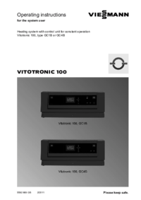
Viessmann VITOTRONIC 100 GC1B Operations Instructions (32 pages)
Brand: Viessmann | Category: Water heaters & boilers | Size: 0.38 MB |

Table of contents
1
8
14
17
25
26
26
28
32

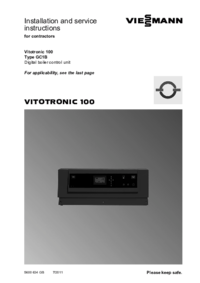
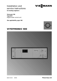
Viessmann VITOTRONIC 100 GC1B Installation Manual (164 pages)
Brand: Viessmann | Category: Water heaters & boilers | Size: 4.17 MB |
Table of contents
58
95
100
103
120
129
130
130
131
158
164

Viessmann VITOTRONIC 100 GC1B Operations Instructions (44 pages)
Brand: Viessmann | Category: Water heaters & boilers | Size: 0.65 MB |
Table of contents
Viessmann VITOTRONIC 100 GC1B Operations Instructions (168 pages)
Brand: Viessmann | Category: Water heaters & boilers | Size: 2.14 MB |
Table of contents
57
92
94
100
104
105
108
110
123
123
129
138
140
141
142
153
157
160
162
163
168

Viessmann VITOTRONIC 100 GC1B Service Manual (132 pages)
Brand: Viessmann | Category: Water heaters & boilers | Size: 3.60 MB |
Table of contents
6
26
37
72
100
108
109
115
117
125
130
131
132
More products and manuals for Water heaters & boilers Viessmann
| Models | Document Type |
|---|---|
| WB2B |
Service Manual
Viessmann WB2B Technical data,
80 pages
|
| VITOCROSSAL 200 |
Installation Guide
Viessmann VITOCROSSAL 200 Installation guide,
44 pages
|
| Vitogas 100 GS1 Series |
Service Manual
Viessmann Vitogas 100 GS1 Series Technical data,
36 pages
|
| KOB PYROT KRT SERIES |
User Manual
Rochester, MI - Southeast Michigan RC&D Council [en] ,
2 pages
|
| Vitodens 100-W WB1B Series |
Operations Instructions
Viessmann Vitodens 100-W WB1B Series Operating instructions,
20 pages
|
| VITOCELL 300-H |
Service Manual
Viessmann VITOCELL 300-H Technical data,
24 pages
|
| VITODENS 300-W |
User Manual
 VIESMANN,
10 pages
VIESMANN,
10 pages
|
| VITODENS 333 |
Operations Instructions
Viessmann VITODENS 333 Operating instructions,
136 pages
|
| Vitocrossal 200 CM2 Series |
Installation Manual
Viessmann Vitocrossal 200 CM2 Series Unit installation,
72 pages
|
| VITODENS 200 WB2B |
Service Manual
Viessmann VITODENS 200 WB2B Technical data,
64 pages
|
| Vitocrossal 300 CT3 SERIES |
Operations Instructions
Viessmann Vitocrossal 300 CT3 SERIES Operating instructions,
12 pages
|
| Vitorond 100 |
Service Manual
Viessmann Vitorond 100 Technical data,
64 pages
|
| VITOCELL 300B |
User Manual
VITOCELL 300 B Installation instructions,
16 pages
|
| Vitocrossal CM2 Series 400 |
Operations Instructions
Viessmann Vitocrossal CM2 Series 400 Operating instructions,
12 pages
|
| WB2B |
Operations Instructions
Viessmann WB2B Operating instructions,
124 pages
|
| WB2B |
Installation Guide
Viessmann WB2B Installation guide,
88 pages
|
| Vitodens 100-W |
Operations Instructions
Viessmann Vitodens 100-W Operating instructions,
48 pages
|
| KOB PYROT KRT SERIES |
Service Manual
Viessmann KOB PYROT KRT SERIES Technical data,
36 pages
|
| Vitogas 100 GS1 Series |
User Manual
Technical Data Manual,
8 pages
|
| Vitotronic 300 GW6B |
Installation Manual
Viessmann Vitotronic 300 GW6B Unit installation,
132 pages
|
Viessmann devices


© 2020, manymanuals.com. All rights reserved. | 0.084 s |
 Manymanuals.com
 Manymanuals.de
 Manymanuals.fr
 Manymanuals.it
 Manymanuals.pl
 Manymanuals.cz
 Manymanuals.es
 Manymanuals-pt.com